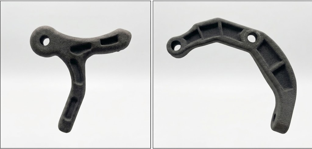
3D Printed Bicycle Brake Caliper
FEA-driven redesign of a Nylon-12 caliper, validated against ISO 4210-2 on a real bike
- Context
- ME 240 — Intro to Design and Manufacturing, Northwestern, Spring 2026
- Role
- FEA lead on a six-person team
- Timeline
- Spring 2026
Brief
Design a two-piece caliper brake — left and right arms rotating about a shared pivot — that clamps the rim via cable tension from the brake lever. Requirements were derived from ISO 4210-2, primarily braking distance in wet and dry conditions, lever force, and brake assembly attachment.
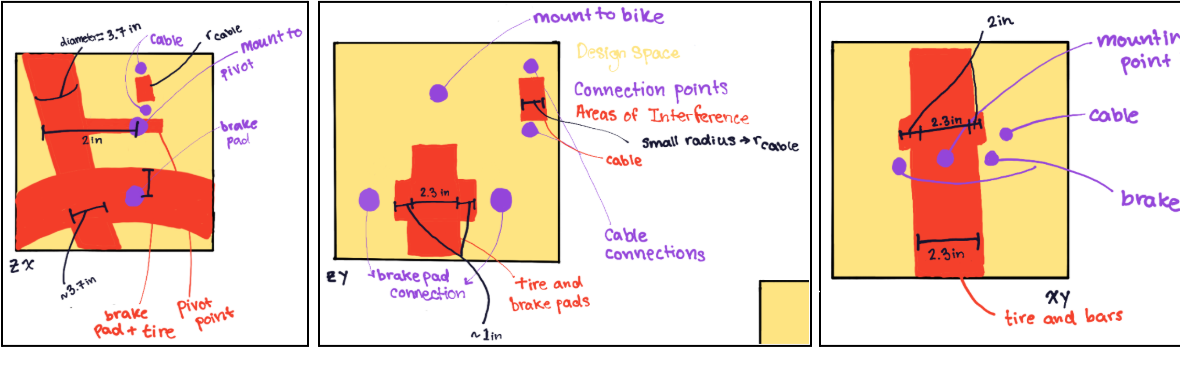
Concept sketches — caliper arm geometry and pivot layout
Loads
Hand calculations related lever input force to cable tension and pad friction force: roughly 126 N normal force and 40 N friction force, from a 60 N input at the lever with a 2:1 lever ratio and a measured coefficient of friction of 0.312.
FEA — First Iteration
Nylon-12 material properties used throughout:
- Young’s modulus: 1850 MPa
- Poisson’s ratio: 0.4
- Max tensile strength: 50 MPa
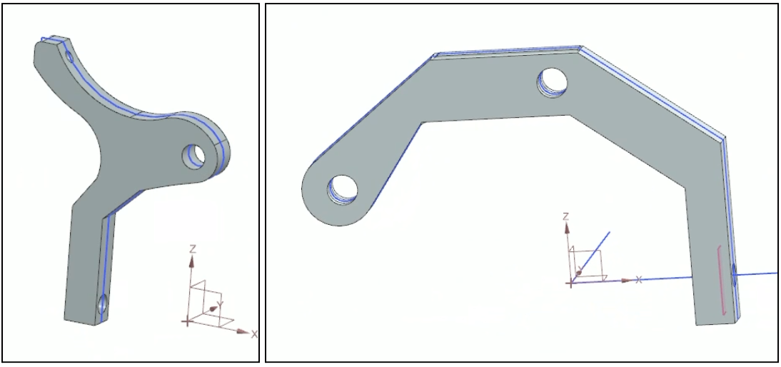
First CAD drafts — initial caliper geometry
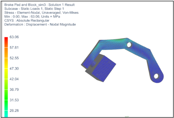
The initial CAD failed. Stress concentrated at sharp corners and rapid geometry changes.
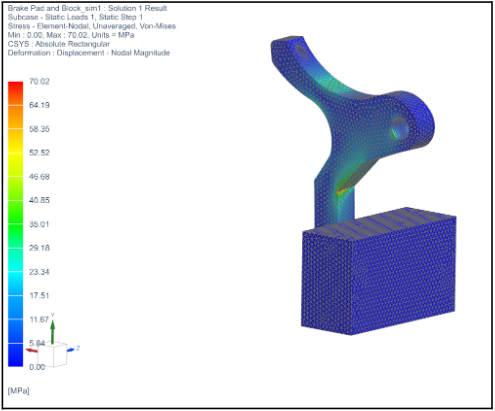
| Metric | Value | Limit | Status |
|---|---|---|---|
| Left peak von Mises stress | 70.02 MPa | 50 MPa | FAIL · FOS 0.71 |
| Right peak von Mises stress | 63.06 MPa | 50 MPa | FAIL · FOS 0.79 |
| Left deflection | 3.585 mm | — | — |
| Right deflection | 5.938 mm | — | — |
| Combined deflection | 9.523 mm | 11 mm | MARGINAL · FOS 1.15 |
Topology Optimization
Ran topology optimization to find the load path. It removed material from the centers of the members while keeping it at the edges — the same principle as an I-beam. This drove shallow divots in the low-stress zones of the next revision.
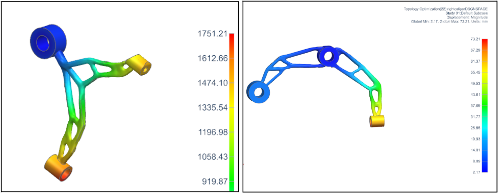
Topology optimization results — load path and material removal zones
FEA — Second Iteration
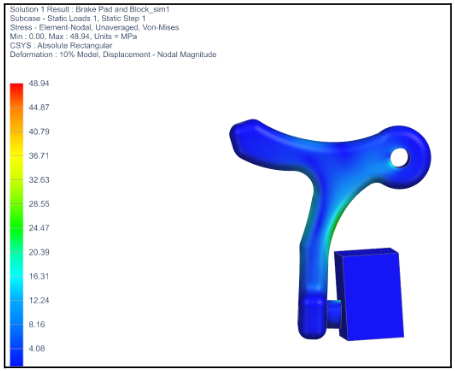
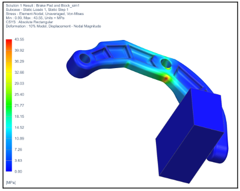
Filleted all corners, increased member thickness, and added the topology-driven divots.
| Metric | Value | Limit | Status |
|---|---|---|---|
| Left peak von Mises stress | 48.94 MPa | 50 MPa | PASS · FOS 1.02 |
| Right peak von Mises stress | 43.55 MPa | 50 MPa | PASS · FOS 1.15 |
| Combined deflection | 5.131 mm | 11 mm | PASS · FOS ≈ 2 |
Peak stresses dropped roughly 30%, and total deflection was cut in half compared to iteration 1.
Physical Testing
Video — on-bike braking test
Round 1 — May 19. Weight 17.2 g (right) / 19.9 g (left). The calipers turned out not to be fully tightened on the first stop; two problems also surfaced: not enough clearance for the right brake pad to screw in fully, so it dragged on the rim at rest, and visible deflection at the brake cable hole under load.
Round 2 — June 2. After adding edge blends, adding material near the cable hole, and removing material so the pad could seat.
| Test | As measured | Corrected @ 25 km/h | ISO Limit | Status |
|---|---|---|---|---|
| Round 1 — dry, untightened | 6.7 m @ 14.3 km/h | 20.5 m | 15 m | FAIL |
| Round 1 — dry, after tightening | 5.56 m @ 15.98 km/h | 13.9 m | 15 m | PASS |
| Round 2 — dry | 6.5 m | 16.3 m | 15 m | FAIL |
| Round 2 — wet | 10.67 m | 20.1 m | 15 m | FAIL |
| Braking force — Round 1 | 124 N | — | — | — |
| Braking force — Round 2 | 125 N | — | — | — |
| Caliper deformation — Round 2 | 7.31 mm | — | 11 mm | WITHIN LIMIT |
| Brake handle displacement — Round 2 | 48.71 mm | — | — | — |
Why It Regressed
Reducing the curve so the brake pad could seat fully increased the pad-to-rim gap on that side. More of the lever force went into closing the calipers rather than clamping the rim, so stopping distance went up. The reduced curve also left less material supporting the pad. A plausible secondary effect: material added near the cable hole may have restricted left caliper travel, and the deflection that was treated as a defect in round 1 may have been helping by rotating the right caliper further into the rim.
Takeaway
The dimensional error that broke round 1 — pad clearance — was invisible to both FEA and topology optimization. Passing simulation is not the same as passing on a bike.
Design for Manufacture
Analyzed producing the caliper in aluminum alloy at three volumes:
- 50,000/yr, entry-level bike — die casting with secondary drilling.
- 10,000/yr, high-performance — forging plus CNC.
- 200/yr, custom frame shop — straight CNC (or metal AM).