Formula SAE Motor Differential Mount
Load-bearing drivetrain mount with an eccentric chain tensioner, from FEA to CNC
- Context
- Northwestern Formula SAE
- Role
- Design, analysis, and manufacturing
- Timeline
- Sep. 2025 – Present
Goal
Design a mount that rigidly locates the motor and differential to the frame, integrate a chain tensioning mechanism, and keep mass as low as possible.
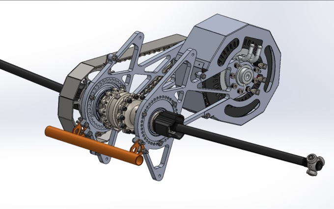
Render — full drivetrain assembly (motor, differential, mounts, chain, halfshafts)
Chain Tensioning
The team chose an eccentric plate over a turnbuckle. A turnbuckle would have split the mount into two pieces, which makes aligning the plates considerably harder.
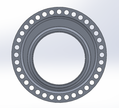
Model — eccentric tensioning plate
- Eccentricity: 0.1875 in
- 27 holes on the mounts against 24 on the plate
- 3 holes align per configuration — 216 distinct tensioning positions
- Plate retained with 3 bolts
Analysis
Assumed a 4 kN chain tensioning force; motor and differential masses came from their datasheets. Free body diagrams of the mount resolved reactions of approximately 3040 N and 960 N at the two supports.
FEA and Redesign
The first FEA iteration showed the two mounts were badly mismatched: the right mount came back at a factor of safety of 1.3 while the left was at 3.1 — one under-designed, one carrying dead weight.
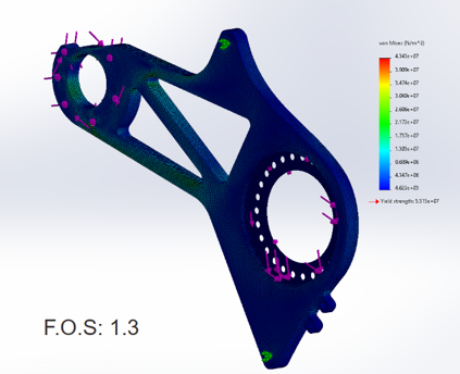
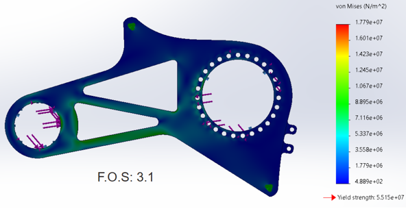
The geometry was reworked into the final design, which significantly reduced mass while bringing both mounts to a factor of safety of at least 1.5.
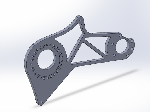
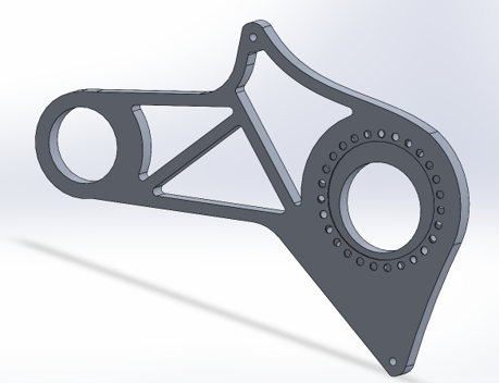
First-iteration mounts — right side FOS 1.3, left side FOS 3.1.
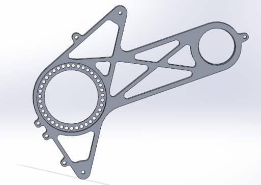
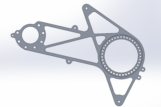
Final mount geometry — reworked to bring both sides to FOS ≥ 1.5, with reduced mass.
Manufacturing
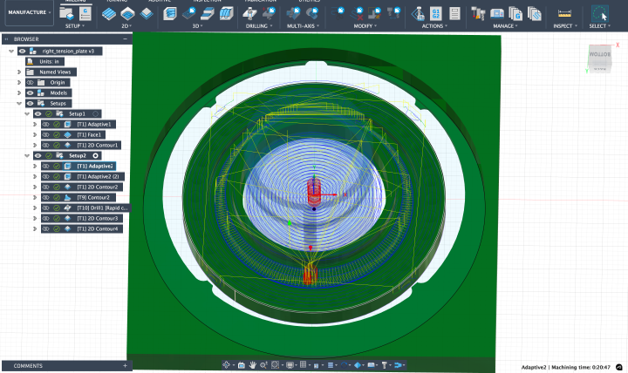
Programmed toolpaths in Fusion 360 CAM and CNC milled each component in-house, including multi-setup operations on the eccentric tension plates.
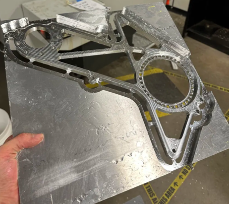
Assembled onto the car with the motor, differential, chain, and halfshafts.
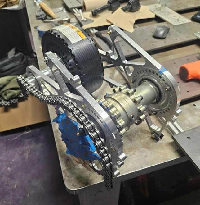
Photo — assembled drivetrain on the bench