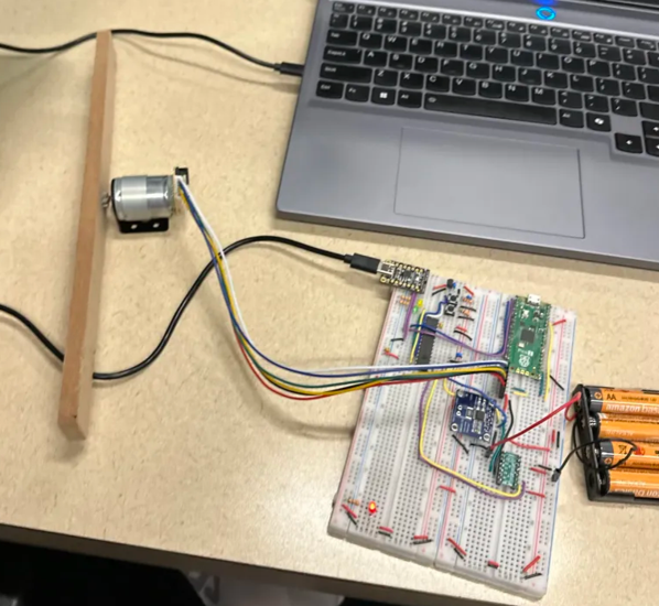
PID Motor Controller
A PIC32 position controller with a Python tuning interface and trajectory tracking
- Context
- Northwestern coursework
- Role
- Individual project — circuit, firmware, and host interface
Goal
Build an interface for testing a brushless DC motor under different PID constants — set raw PWM, set PID gains, hold a commanded encoder angle, follow a step reference, and follow a cubic trajectory.
Hardware
A PIC32 and a Pico 2 driving the motor through an H-bridge, with an INA219 current sensor and a quadrature encoder. Designed the circuit diagram first, supporting both I2C and UART.
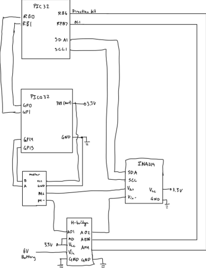
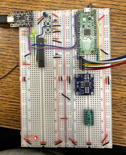
Wired and bench-tested with an oscilloscope to verify voltages and currents, with indicator LEDs confirming which components had power.
Communication Architecture
UART from a Python script on the laptop to the PIC32, carrying a single-character menu protocol. I2C between the current sensor and the Pico 2. Each menu command maps to a case in the firmware loop — for example, one returns current in mA from the INA219, another requests the encoder count over a second UART link and returns it to the client.
while(1)
{
    NU32DIP_ReadUART1(buffer, BUF_SIZE); // we expect the next character to be a menu command
    NU32DIP_YELLOW = 1;                  // clear the error LED
    switch (buffer[0]) {

        // get current in mA
        case 'b':
        {
            sprintf(buffer, "%f\r\n", INA219_read_current());
            NU32DIP_WriteUART1(buffer);  // send current info to client
            break;
        }

        // get encoder value
        case 'c':
        {
            WriteUART2("a");
            // reading encoder value
            while (!get_encoder_flag()) {}
            set_encoder_flag(0);
            sprintf(buffer, "%d\r\n", get_encoder_count());

            NU32DIP_WriteUART1(buffer);  // send encoder count to client
            break;
        }
Trajectory commands read a point count, then stream the reference points in, then run the tracking loop and send the recorded position data back for plotting.
// set cubic angle reference
case 'n':
{
    int n = 0;
    int i = 0;

    // reads in number of input points
    NU32DIP_ReadUART1(buffer, BUF_SIZE);
    sscanf(buffer, "%d\r\n", &n);

    set_n(n);

    for (i = 0; i < n; i++) {
        float ref = 0;
        NU32DIP_ReadUART1(buffer, BUF_SIZE);
        sscanf(buffer, "%f\r\n", &ref);

        set_ref(ref, i);
    }
    break;
}

// track trajectory
case 'o':
{
    OC1CONbits.ON = 1;    // turn on OC1
    T2CONbits.ON = 1;     // turn on Timer2

    set_mode(TRACK);
    while (get_mode() == TRACK) {}

    // send over plots
    position_plot();

    break;
}
Results
The cubic reference tracking test produced near-perfect overlap between reference and measured angle across a roughly 180° to -95° swing, scoring 0.4525.
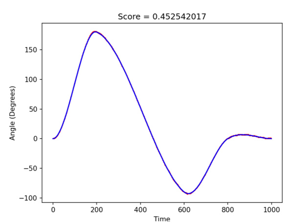
Plot — cubic trajectory tracking, reference vs. measured angle