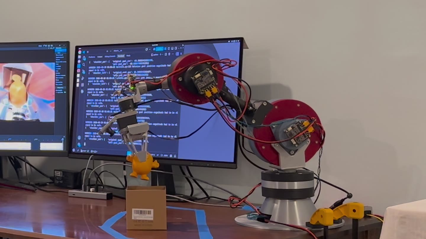
5-DOF Robotic Arm
A brushless arm with 3D-printed cycloidal reducers that learned pick-and-place through imitation learning
- Context
- Independent project
- Role
- Individual project — mechanical design, actuation, electronics, and learning pipeline
- Timeline
- Summer 2026 – Present
Goal
Design and build a 5-degree-of-freedom robotic arm from scratch that completes a pick-and-place task, first under teleoperation and then autonomously with a policy trained on those demonstrations.
Requirements
Functional
- Five independently actuated rotational degrees of freedom.
- Complete a pick-and-place task: approach, grasp, transport, and release a target object.
- A 0.4 kg design payload at the tool center point (TCP).
- A 400 mm reach, measured from the base yaw axis to the TCP.
- Capture teleoperated demonstrations and reproduce the task autonomously through imitation learning.
Mechanical
- Every joint holds at least a 1.2× torque margin over its worst-case static holding torque.
- A mass budget of 0.06 kg per link (carbon-fiber tube plus printed clamps).
- Joint gearboxes couple to one another without an axial offset that would create a large parasitic moment.
Electrical
- All five actuators share a common power rail and a single CAN-FD bus in a daisy-chain topology.
- Absolute rotary position feedback at every joint.
- Controller mounting can’t interfere with the motor body geometry or the rotor magnet standoff.
Software
- Demonstration recording, ACT policy training, and inference all run on the LeRobot stack.
- Each joint is commissioned through the moteus tooling: calibration, plus position, velocity, and torque control modes.
Mechanical Architecture
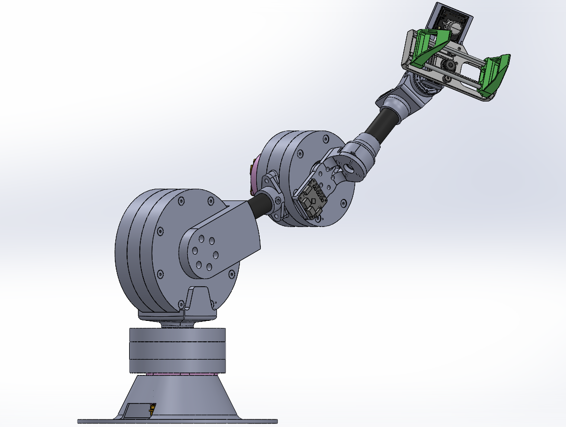
CAD — full assembly, SolidWorks
The arm uses two actuator families. The three proximal joints carry most of the load, so they use MJ5208 brushless motors driven by moteus r4.11 controllers through custom cycloidal reducers. The two distal joints use SteadyWin GIM3505-8 integrated gearmotors driven by moteus-c1 controllers.
| Joint | Function | Motor | Controller | Reduction |
|---|---|---|---|---|
| J1 | Base yaw | MJ5208 | moteus r4.11 | 15:1 custom cycloidal |
| J2 | Shoulder pitch | MJ5208 | moteus r4.11 | 30:1 custom cycloidal |
| J3 | Elbow pitch | MJ5208 | moteus r4.11 | 15:1 custom cycloidal |
| J4 | Forearm roll | GIM3505-8 | moteus-c1 | 8:1 integrated planetary |
| J5 | Wrist roll | GIM3505-8 | moteus-c1 | 8:1 integrated planetary |
J1 rotates the entire arm about the vertical axis. J2 is the highest-torque joint and drives the first link, and J3 drives the second. The forearm roll (J4) sits at the elbow rather than at the wrist.
Actuation
MJ5208 (J1–J3)
The MJ5208 is a brushless motor from mjbots, wound at 330 Kv and designed to pair with moteus controllers. It’s a bare motor with no gearbox and no encoder, which is why J1–J3 need custom cycloidal reducers and a separately mounted diametric magnet.
| Parameter | Value |
|---|---|
| Peak torque | 1.7 N·m |
| Peak power | 600 W |
| Kv | 330 rpm/V |
| Maximum speed | 7500 RPM |
GIM3505-8 (J4–J5)
The GIM3505-8 is an integrated 8:1 planetary gearmotor with an onboard 14-bit magnetic encoder. The wrist joints see far lower torque than the shoulder and elbow, so an off-the-shelf integrated unit works here instead of a custom reducer. That saves both design time and distal mass. The specifications below are from the manufacturer’s GDZ-driver planetary reduction motor selection table.
| Parameter | Value |
|---|---|
| Gear ratio | 8:1 |
| Gearbox type | Planetary, aluminum gears |
| Rated torque (output) | 0.67 N·m |
| Peak torque (output) | 1.79 N·m |
| Rated speed (output) | 230 RPM |
| Maximum speed (output) | 400 RPM |
| Rated voltage | 24 V |
| Operating voltage range | 12–40 V |
| Rated power | 36.72 W |
| Rated current | 1.53 A |
| Peak current | 3.99 A |
| Torque constant | 0.44 N·m/A (output-referenced) |
| Speed constant | 16.67 rpm/V (output-referenced) |
Torque headroom at the wrist
The 0.67 N·m continuous rating is generous for this application. A 0.2 kg payload weighs 1.96 N, so it demands about 0.20 N·m at J5 for every 100 mm between the J5 axis and the payload’s center of mass. J5 therefore stays within its continuous rating out to about 340 mm of offset, far beyond anything the wrist geometry will produce. The wrist joints aren’t the constraint on this arm. The shoulder is.
Driver substitution: moteus-c1 in place of the GDZ34
The GIM3505-8 normally ships with a GDZ34 integrated driver. I replaced it with a moteus-c1 so that every joint runs the same firmware, the same CAN-FD bus, and the same torque-control interface. Because the moteus-c1 commutates the rotor directly, the motor has to be characterized at the rotor rather than at the output.
Integration between the GIM3505-8 and moteus-c1
The GIM3505-8 can be ordered with an AS5047P encoder, the same encoder the moteus-c1 carries onboard. The external encoder connects to the controller’s AUX2 port, and the controller’s three phases connect to the motor’s three phases.
| AUX2 pad | 5 | 3 | A | B | C | D | G |
|---|---|---|---|---|---|---|---|
| Encoder pin | 5V | unused | SCK | MISO | MOSI | CS | GND |
The c1 also has to be configured to turn off its onboard encoder and read the one on the GIM3505-8 instead. These commands in the moteus controller terminal make that change:
conf set aux1.spi.mode 1
conf set aux2.pins.0.mode 1
conf set aux2.pins.1.mode 1
conf set aux2.pins.2.mode 1
conf set aux2.pins.3.mode 2
conf set aux2.spi.mode 2
conf set aux2.spi.rate_hz 12000000
conf set motor_position.sources.0.aux_number 2
conf set motor_position.sources.0.type 1
conf set motor_position.sources.0.cpr 16384
conf set motor_position.sources.0.reference 0
conf set motor_position.commutation_source 0
conf set motor_position.output.source 0
conf set motor_position.rotor_to_output_ratio 0.125
conf write
Cycloidal Reducer Design
I developed two reducer designs: a 30:1 unit for the shoulder, and a 15:1 unit built twice for the base yaw and the elbow. Both follow the same layout. Twin cycloidal discs are mounted 180° out of phase to cancel the eccentric imbalance, driven by a hex input shaft against ring rollers on pins, with the output taken through a circle of roller pins.
| Parameter | 30:1 (J2 shoulder) | 15:1 (J1 base yaw, J3 elbow) |
|---|---|---|
| Ring diameter | 120 mm | — |
| Ring rollers | 31 × Ø10 mm | 16 × Ø10 mm |
| Camshaft diameter | 20 mm | 10 mm |
| Output rollers | 8 × Ø10 mm on an 80 mm pin circle | 6 × Ø10 mm |
| Cycloidal discs | 2 discs, 8 mm thick, 180° apart | 2 discs, 180° apart |
| Eccentricity | 1.0 mm | — |
| Profile coefficient K1 | 0.52 | — |
| Disc center hole | — | ~20 mm |
| Output roller holes | — | ~12 mm |
| Input | Hex shaft | 5 mm hex shaft |
| Cam | — | 3D printed |
| Disc material | PLA or PETG (selection pending) | — |
| Assembly mass | ~1.32 kg with motor and controller | — |
The 30:1 cam assembly uses two eccentric bearings (one per disc) plus two support bearings in line with the input axis. That way the eccentric loads are supported on both sides instead of cantilevered. The two 15:1 units are built from a common template.
Electronics and Control
Bus topology
All controllers share one power rail and a single CAN-FD daisy chain. Three moteus r4.11 controllers drive J1–J3, and the moteus-c1 controllers for the wrist join the same bus.
| Parameter | moteus r4.11 (J1–J3) | moteus-c1 (J4–J5) |
|---|---|---|
| Voltage input | 10–44 V | 10–51 V |
| Peak phase current | 100 A | 20 A |
| Continuous phase current (uncooled) | 12 A | 5 A |
| Continuous phase current (cooled) | 32 A | 14 A |
| Peak electrical power | 900 W @ 30 V | 250 W @ 28 V |
| Mass | 14.2 g | 8.9 g |
| Dimensions | 46 × 53 mm | 38 × 38 × 9 mm |
| CPU | STM32G4 | STM32G4 |
| Communications | 5 Mbps CAN-FD | 5 Mbps CAN-FD |
Both boards run the same firmware image and use the same power, CAN, and AUX2 connectors, so the mixed r4.11 / c1 chain looks like one uniform bus from the host’s point of view.
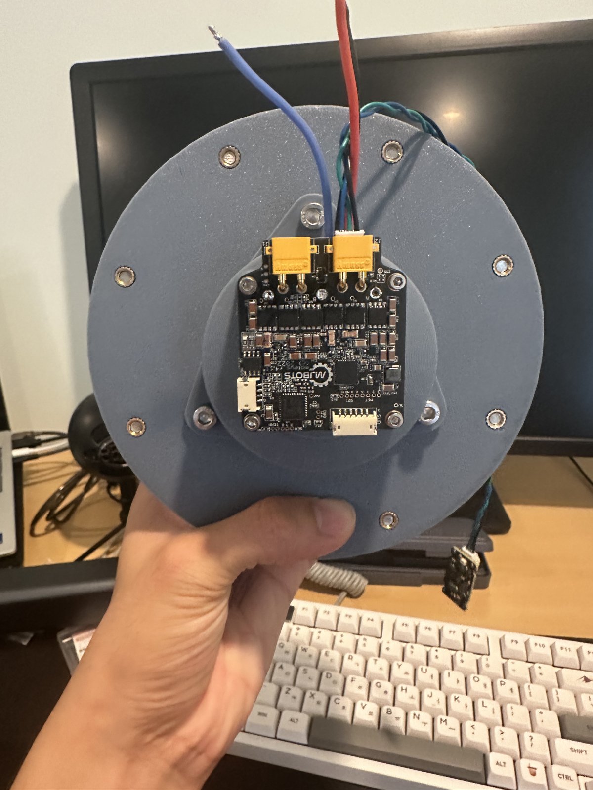
Photo — moteus r4.11 mounted on the back of a reducer housing
Position feedback
- J1–J3 use the standard moteus on-axis magnetic encoder, with a diametric magnet mounted on the stator-side axle. That keeps sensing on the motor side of the reducer.
- J4–J5 wire the GIM3505-8’s own motor-side AS5047P to the moteus-c1 instead of using the AS5047P already on the c1. This avoids the magnet standoff problem, because the motor’s factory encoder is already correctly spaced from its own rotor magnet.
Each motor-controller pair is calibrated with moteus_tool --calibrate before any closed-loop position control. Calibration establishes the commutation offset and encoder mapping.
Software and Learning Stack
The arm is controlled through imitation learning, not classical trajectory planning:
- Record teleoperated demonstrations of the pick-and-place task.
- Train a policy on those demonstrations with LeRobot.
- Run inference on the trained policy, with the arm executing autonomously.
That choice drove hardware requirements upstream. Teleoperation needs smooth, backdrivable-feeling torque control, and the control loop needs consistent timing. That’s why every joint runs a moteus controller with onboard closed-loop control rather than a step/direction driver.
Development and Test Log
This log covers the build, test, and integration work from 20 August to 21 September 2026: revising the 30:1 reducer, building the first 15:1 reducer, testing reducer output torque, integrating the full arm, and reaching the first autonomous completion of the pick-and-place task.
30:1 Reducer Revision (J2) — 20 to 22 August 2026
The first version of the 30:1 reducer had significant backlash. I found two contributing causes and made one design change for each:
- Disc-to-ring clearance. I reprinted the cycloidal discs slightly oversized to take up clearance between the disc profile and the ring rollers.
- Roller pin fit in the input wall. I reprinted the input wall with press-fit rather than loose-fit holes for the roller pins.
The loose-fit pin holes were the bigger cause. Under load, the cycloidal disc pushes against the roller bearings, and a loose hole lets the pin behind each bearing shift slightly. On a change of direction, the disc travels through that free play before it re-engages the rollers, and that shows up at the output as backlash.
On 21 August, I printed and fit-tested most of the revised parts and settled on these print compensations for my printer:
| Feature | Setting | Result |
|---|---|---|
| Cycloidal disc profile | +0.1 mm outward offset | Best fit of the offsets tested |
| Input wall roller pin holes | 5 mm nominal (no offset) | Press fit on the 5 mm pins |
After reassembly on 22 August, backlash was noticeably lower than in the first version. I judged this by hand and haven’t measured backlash quantitatively yet.
Video — checking backlash by hand on the revised 30:1, input held fixed while the output arm is rocked
15:1 Reducer Build (J1, J3) — 22 August to 2 September 2026
Before printing, I added part identifiers to the CAD model to simplify assembly.
| Date | Activity | Finding / outcome |
|---|---|---|
| 23 Aug | Printed most of the reducer parts. | The shoulder bolts that secure the outer walls were a very tight fit in the printed parts. |
| 24 Aug | Completed the first full assembly. | The input shaft was hard to turn, pointing to excess friction, likely from a camshaft component rubbing against the output flange. |
| 25 Aug | Disassembled the reducer for inspection. | Revised the CAD to correct the fits and reprinted the affected parts. |
| 26 Aug | Reassembled the reducer. | With the shoulder bolts fully tightened, the hex input shaft still bound. Loosening the shoulder bolts restored free rotation. |
Reducer Output Torque Testing — early September 2026
For each configuration, I commanded a fixed input torque at the motor and measured the resulting force with a digital force gauge at a known radius from the output axis. Output torque is force times radius, and the ideal output is the commanded input torque times the reduction ratio. I tested the bare motor first to establish a baseline.
| Unit | Input torque (N·m) | Force (N) | Radius (m) | Output torque (N·m) | Ideal output (N·m) | Output / ideal |
|---|---|---|---|---|---|---|
| Bare motor | 0.20 | 3.0 | 0.075 | 0.225 | 0.20 | 1.13 |
| 15:1 reducer | 0.20 | 33.5 | 0.100 | 3.35 | 3.00 | 1.12 |
| 15:1 reducer | 0.10 | 15.5 | 0.100 | 1.55 | 1.50 | 1.03 |
| 30:1 reducer | 0.10 | 28.7 | 0.100 | 2.87 | 3.00 | 0.96 |
Interpretation. The bare motor produced about 12.5% more torque than commanded. That means the controller’s torque estimate, which comes from the configured torque constant, under-reports actual torque at this operating point, and it explains why the 15:1 results exceed the ideal. Dividing each reducer result by the baseline factor of 1.125 gives a corrected transmission ratio of about 0.99 for the 15:1 at 0.2 N·m, 0.92 for the 15:1 at 0.1 N·m, and 0.85 for the 30:1 at 0.1 N·m. The 30:1 reducer has the largest loss.
Limitations. Each value is a single static measurement, not a dynamic efficiency. The baseline was only measured at 0.2 N·m, so correcting the 0.1 N·m results assumes the same factor holds at the lower torque. All tests ran at low input torque compared with continuous holding torque, so they characterize the efficiency of the custom gearboxes more than they confirm the J2 torque budget.
Arm Integration and Wiring — September 2026
Full assembly of the 5-DOF arm began after reducer testing. The main work items were:
- Structural parts. I printed all the structural parts. The carbon-fiber tube coupler printed poorly at first, and the vertical hole for its M2.5 heat-set insert came out oblong. Adjusting the printer parameters and reducing the hole diameter in CAD produced a hole that fit the insert. I cut the carbon-fiber tubes to length.
- Input shafts. I cut the hex input shafts to length with a rotary tool (Dremel).
- J1–J2 connector. The J1–J2 connector interfered with part of the J1 gearbox interface, so I redesigned it.
- Power distribution. I made custom soldered Y-splitter cables to daisy-chain power between the moteus r4.11 and moteus-c1 controllers.
- GIM3505-8 wiring. I extended the gearmotors’ phase leads, splicing 16 AWG to 26 AWG wire with solder joints and heat-shrink tubing, and re-crimped the encoder wires to the JST-GH connector the moteus-c1 requires.
- Controller configuration. I configured each moteus-c1 to read the external AS5047P encoder on AUX2, using the configuration above.
Video — hardware walkaround during integration: base wiring, joint housings, and a moteus-c1 mounted on a GIM3505-8
CAN-FD Bus Debugging — 13 September 2026
Communication on the CAN-FD bus was intermittent, and slightly pulling or pushing on the wiring was enough to break it. That pointed to faulty crimps and solder joints in the custom daisy-chain harness and its soldered JST-PH connectors.
I checked the bus with python -m moteus.moteus_tool -s, which reports every controller that responds, to confirm whether each controller along the chain could be reached. After I re-soldered the connectors and re-crimped the faulty wires, communication through the entire arm was consistently reliable.
End Effector and Final Assembly — 14 to 15 September 2026
I adopted an open-source gripper with an integrated camera as the end effector and designed a custom connector to mount it to the J5 actuator. The camera provides the visual input the learned policy needs. I finished the gripper and the full arm assembly on 15 September and started building the robot controller framework in LeRobot the same day.
Software Development and Policy Training — 16 to 21 September 2026
I developed the software in this order:
- Tuned the PID gains of each joint.
- Set software joint limits.
- Implemented teleoperation, first with a keyboard and then with an Xbox controller.
- Practiced the pick-and-place task under Xbox-controller teleoperation.
- Recorded 30 demonstration episodes of the pick-and-place task.
- Trained an Action Chunking with Transformers (ACT) policy on the recorded demonstrations, with a batch size of 16 for 75k steps.
Video — teleoperating the arm with an Xbox controller
Video — timelapse of a demonstration-recording session
Result
The trained policy completed the pick-and-place task autonomously in 9 of 10 trials. With only ten trials, this result should be treated as preliminary.
| Evaluation parameter | Value |
|---|---|
| Policy | ACT |
| Training demonstrations | 30 |
| Training | Batch size 16, 75k steps |
| Evaluation trials | 10 |
| Successful trials | 9 |
| Success rate | 90% |
Video — trained ACT policy running pick-and-place autonomously
Fabrication Constraints
Everything in this design had to be buildable with the tools I had on hand, which shaped the mechanical design from the start:
- 3D printer: all structural housings, cycloidal discs, cams, and clamps.
- Set screws: shaft and hub retention.
- Heat-set inserts: every threaded interface in printed parts (15 M5 inserts per 15:1 reducer).
Epoxy bonding, machined inserts, and subtractive machining weren’t available. Every load path therefore has to end in a bearing, a heat-set insert, or a printed feature, which is the main reason the reducers use pins and rollers instead of pressed-in or bonded assemblies.